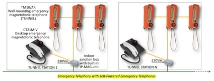
| Emergency Telephony with Self-Powered Emergency Telephones |
Building Block Typical Diagram
Features:
• Fully integration with ECP (Emergency Call Points) Emergency Telephone System.
• Centralized ASTRO Call Manager provided in back-up configuration (one in the Main Control Center and the other one in Back-Up Control Center).
• SIP trunking Wi-Fi interface with the on-board intercom system.
• Real-time monitoring & fault reporting.
• Remote configuration and diagnostics from the Control Center through a suitable PC workstation with relevant software.
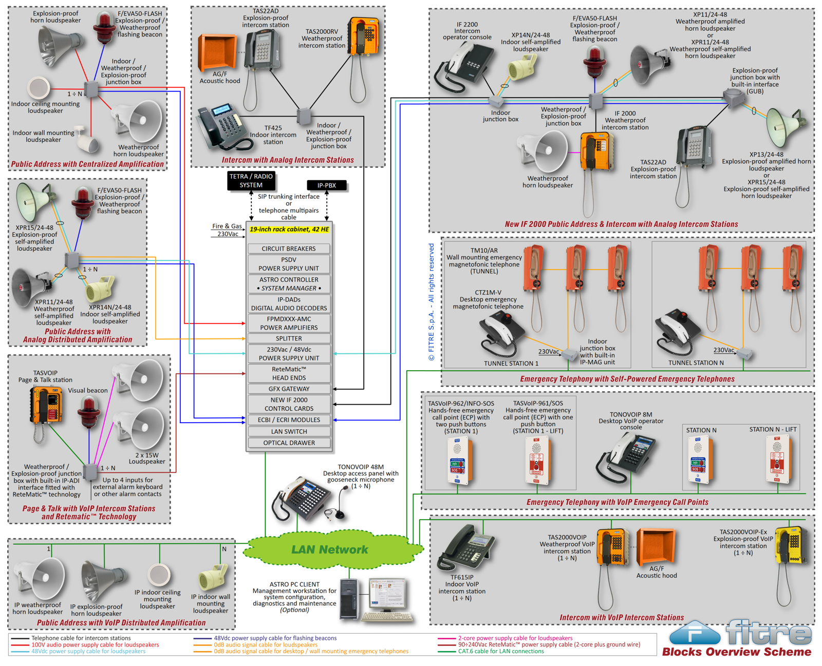
• Emergency telephones usually installed in the tunnels consisting of self-powered telephones with call generator connected in parallel on the same two wires cable and not requiring any kind of power supply.
• In case of normal system operation, all emergency calls coming from the self-powered emergency telephones are addressed (through the station IP-MAG unit and the LAN network) to the relevant Control Center digital operator console.
• In case of IP-MAG unit and/or LAN network fault as well as in case of station complete power supply loss, all emergency calls coming from the self-powered emergency telephones are automatically addressed to the station emergency self-powered operator console and in parallel also to the extreme emergency self-powered operator console of the next station, so as to guarantee the full redundancy of the station emergency self-powered operator console.
• Maximum distance between two self-powered emergency telephones (or operator consoles) of 6-8 kilometres depending on the size of the copper cable (typically, it is recommended a twisted pair 2 x 1.5 mm˛).
• System architecture allowing, in case of fault of a field device, the complete operation of all other field devices even in case of multiple fault events.
 Building Blocks System Concept > > Emergency Telephony with Self-Powered Emergency Telephones Building Blocks System Concept > > Emergency Telephony with Self-Powered Emergency Telephones
| the main Building Blocks types |
|